
BUILD STORY // SALT & PEPPER CADDY // V1.0.0
Sometimes the small problem wins.
World hunger can wait. Salt and pepper dust all over my kitchen table was annoying me enough that it became a tiny 3D project — and, almost accidentally, a good example of the whole D4Maker process from idea to release.
WHAT WORKED ON MY TABLE
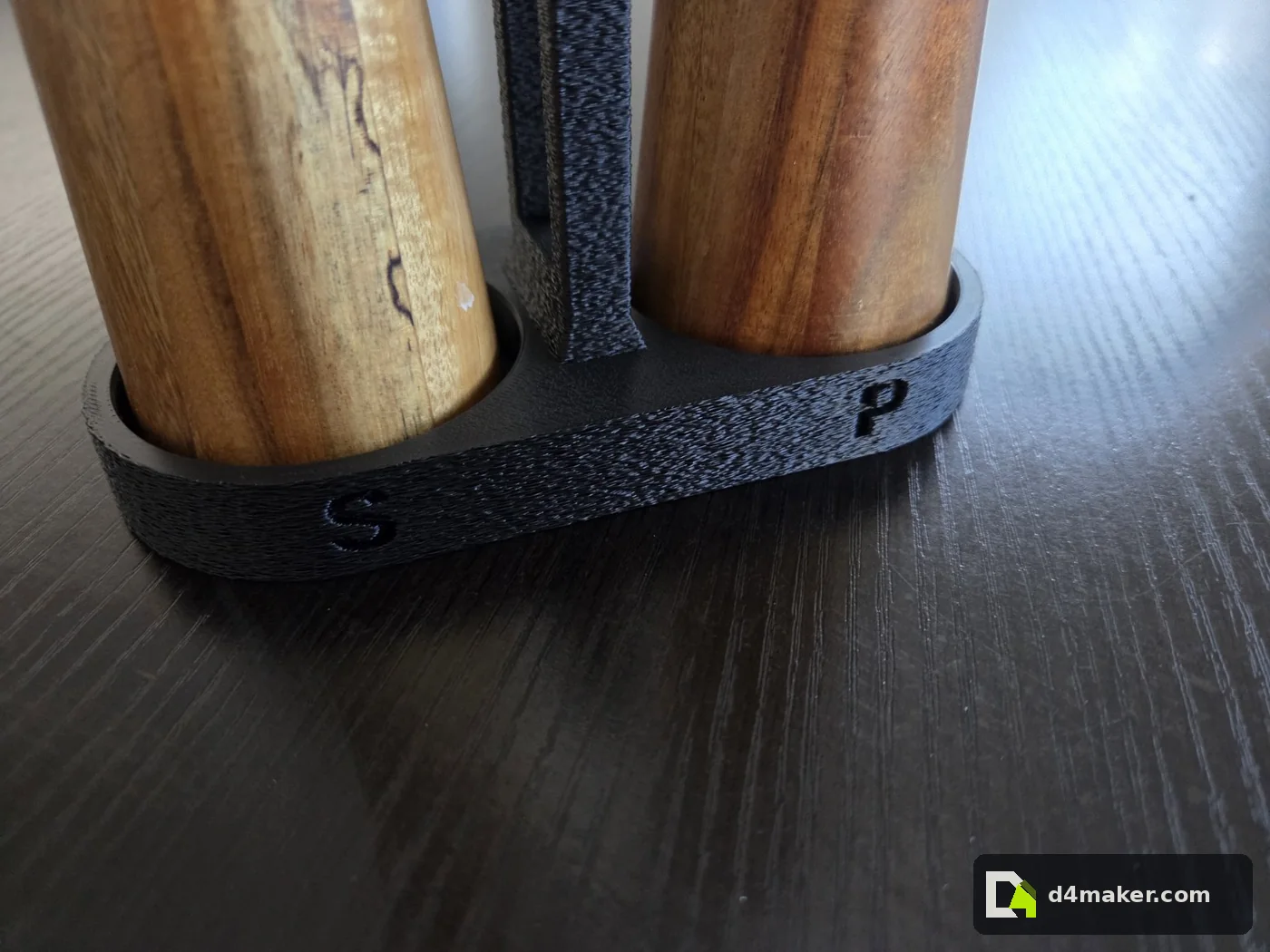
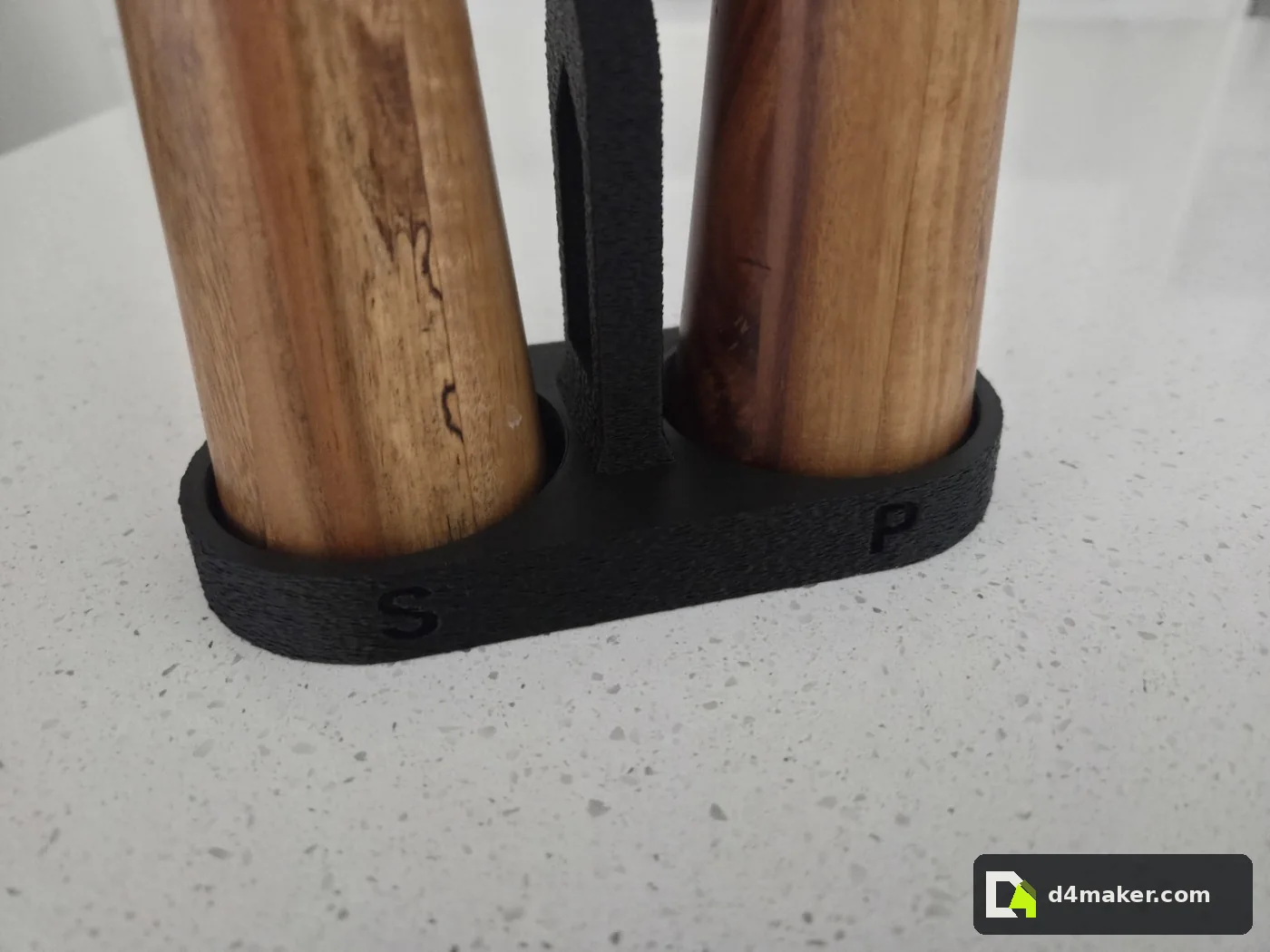
Mine printed without supports and fitted the 55 mm grinders. The holes are 58 mm across and 12 mm deep, with a compact 72 mm grip. A different size still needs its own fit check.
The saved print settings and photos follow. Customise the caddy → · See its BuildBook →
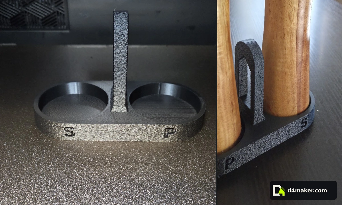
1. The requirement was basically: stop making a mess.
This was not born from a five-page design brief. I had two salt and pepper grinders sitting on the kitchen table and they kept leaving little piles of salt, pepper and general grinder dandruff behind them.
I could have continued wiping the table like a normal person. Instead, my brain decided the obviously sensible answer was to design a tiny bit of plastic specifically for the job.
PICTURES → A MODEL I COULD MEASURE
2. Multiple views made the idea easier to model.
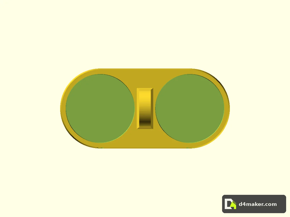
Once the problem and intended use were clear, I explored the form with AI-generated concept renders from multiple angles. The views helped me settle on two wells, a compact bridge, a centre grip and recessed S/P identification before translating the idea into a model whose sizes I could change. Starting with a shared visual target worked better here than jumping from a sentence straight into CAD.
The pictures helped us settle on the shape. MakerMouse, my AI assistant, helped turn that idea into a model. The real grinder measurements and the actual print told us whether it worked; the concept pictures couldn’t do that.
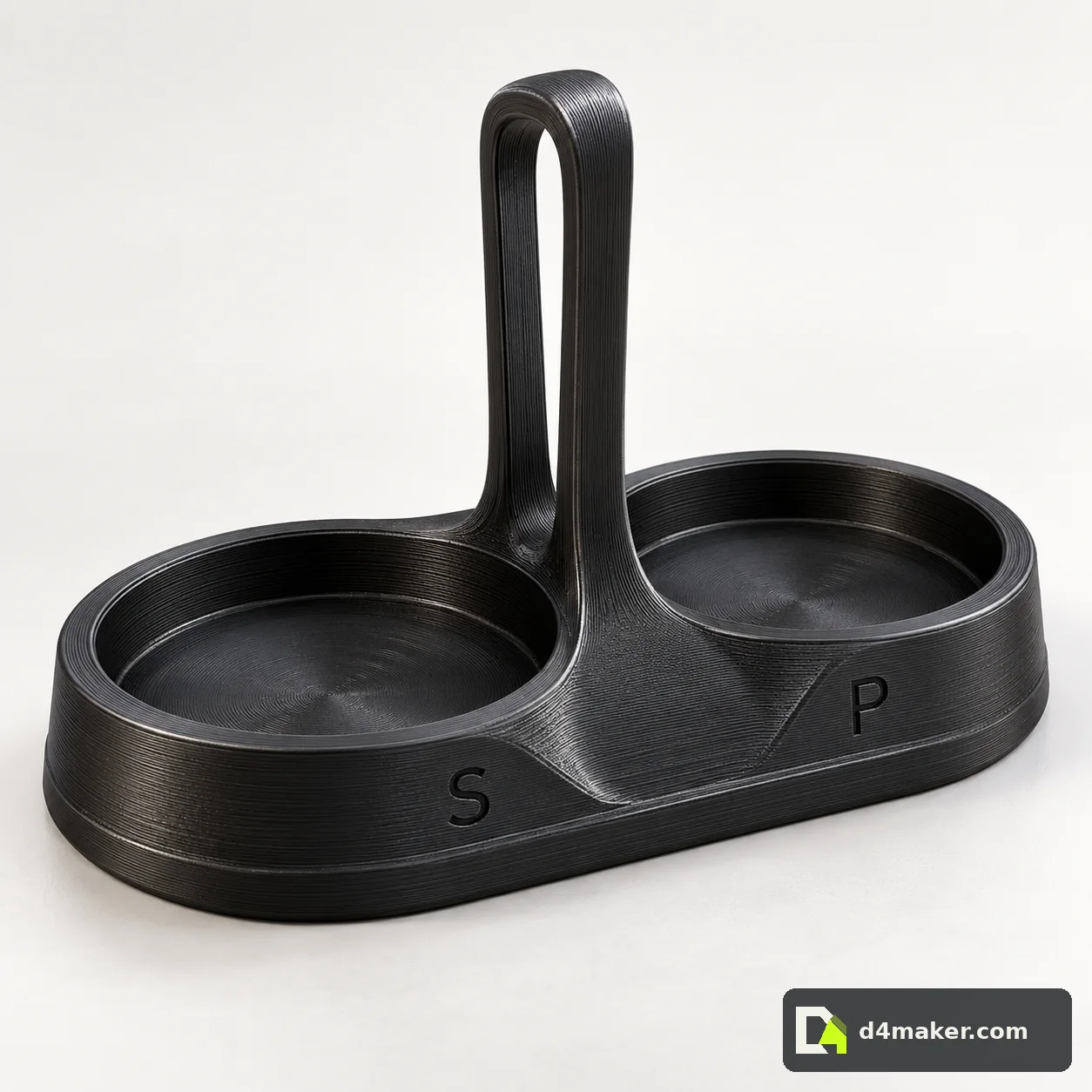
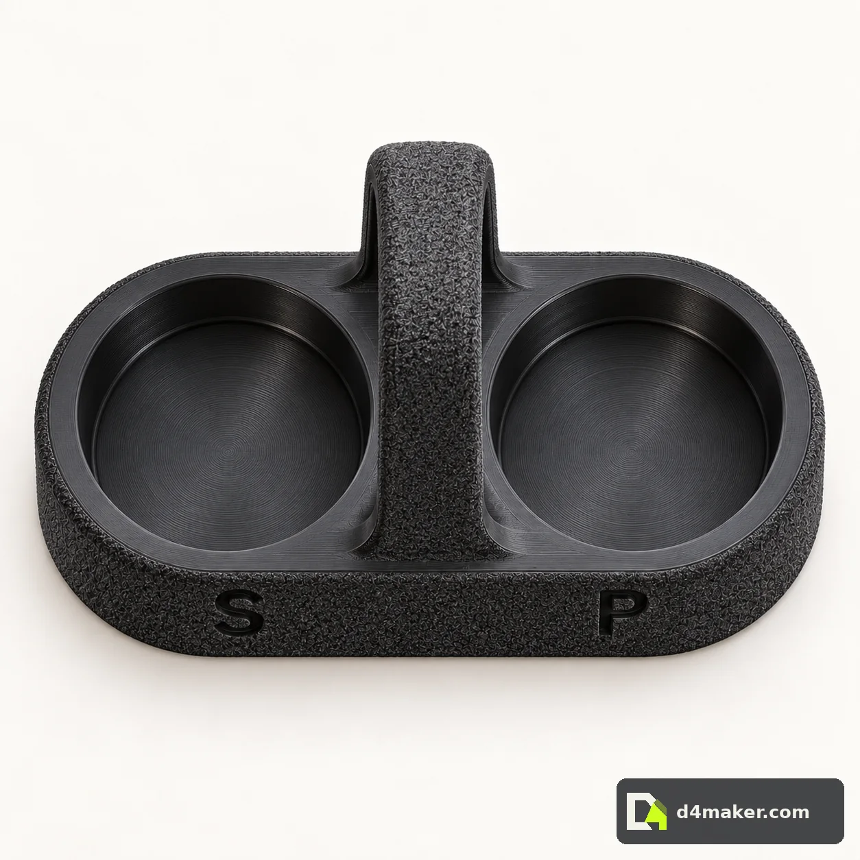
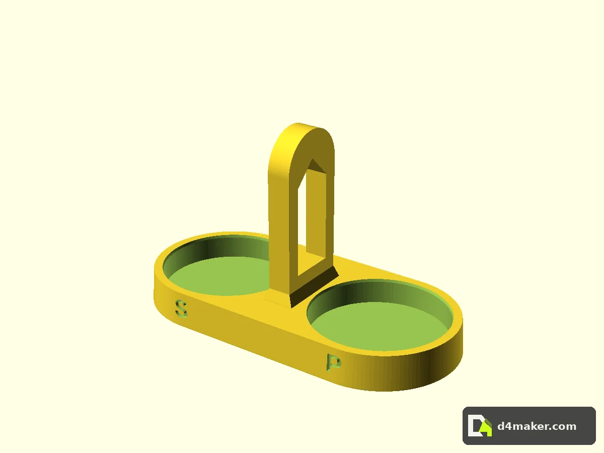
3. Translate the views into measured CAD.
The real grinders were roughly 55 mm across. A perfectly matched 55 mm hole would have looked lovely in CAD and probably been irritating in real life, so the working target became at least 57.5 mm.
I rounded that to 58 mm wells. That gave enough room to put the grinders in and take them back out without having to line them up like docking a spacecraft.
The overall shape stayed compact: two wells side-by-side, a small grip area, and recessed S and P markings so either side of the table could identify the grinders.
PRINT → LOOK → ADJUST
4. V0.1.0 proved the idea. Physical parts decided what happened next.
The first proper prototype proved the overall layout and fit concept. It also reminded me why a render is not validation. Once the part exists, you can feel the proportions, see the seam, inspect the fuzzy skin, try the grip and decide whether the tray actually catches what it was meant to catch.
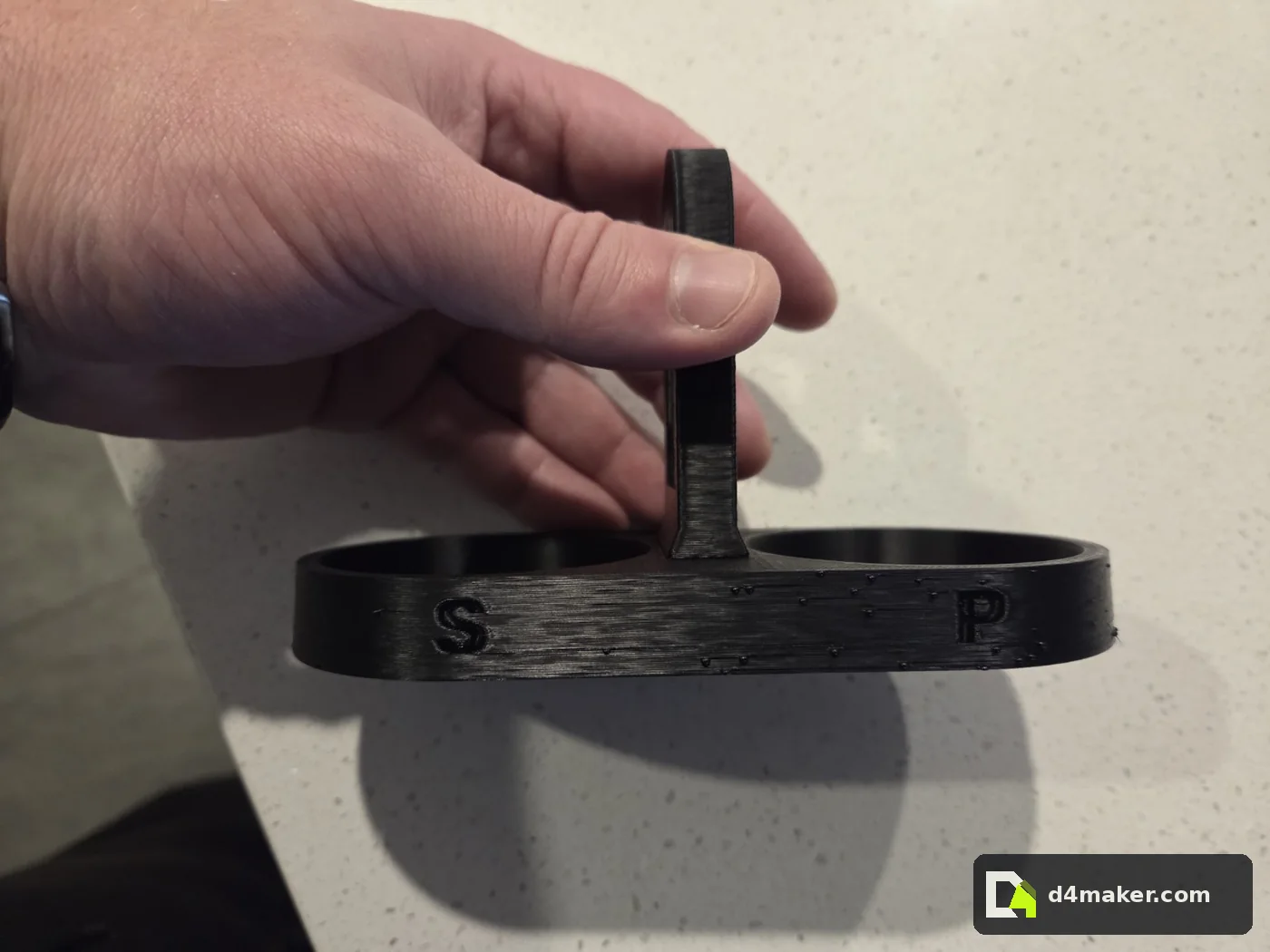
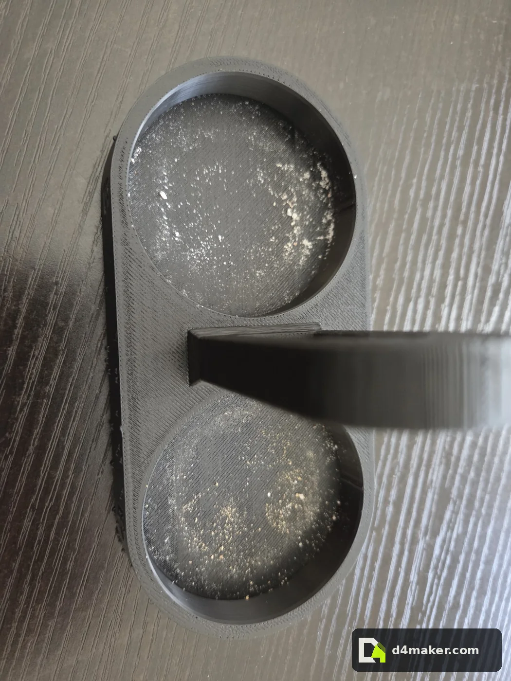
V0.1.1 pushed the wells to 12 mm deep while retaining a 4 mm floor. The underside recesses were deepened to 0.9 mm, the dual-side lettering was refined, and the proven 58 mm pocket fit stayed put.
Wide enough not to fight the grinders, deep enough that they feel parked rather than balanced on a saucer, and still small enough to sit on the table without becoming furniture.
5. The finish mattered more than I expected.
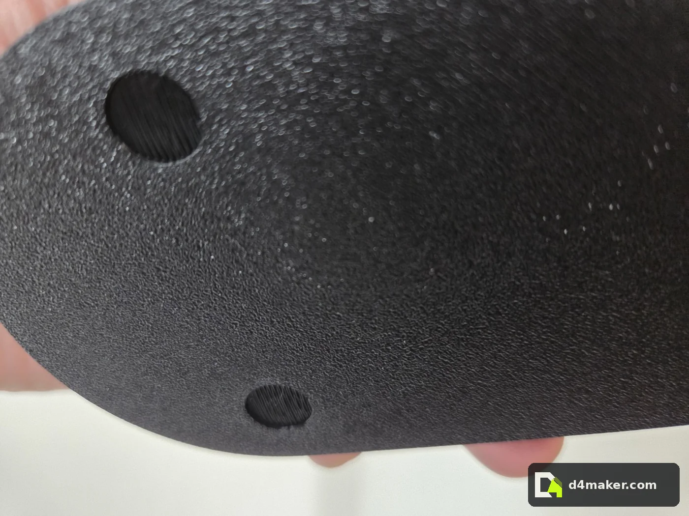
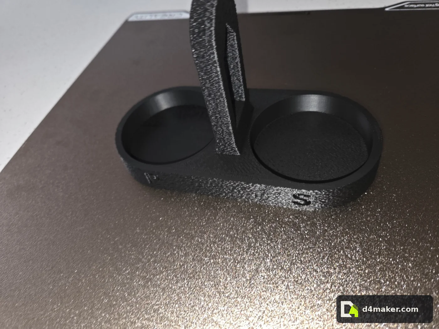
Because the final caddy was going to be black, a completely smooth FDM wall risked looking like... well, a black plastic box. I wanted a slightly textured finish so the object looked intentional rather than like it had just fallen out of a printer.
The final recreated release profile uses Contour fuzzy skin with 0.3 mm thickness and 0.8 mm point distance, using the Displacement generator and Classic noise. That is noticeably stronger than my earlier tuning notes — and it is the profile I saved after reproducing the successful print.
That last bit matters. I did not want texture inside the 58 mm wells making the fit unpredictable, and I definitely didn't want it chewing up the recessed S/P lettering. The functional surfaces stayed smooth; the outside got the texture.
6. Print it the boring way. That's a compliment.
The model was deliberately built to print support-free in its supplied orientation. No clever balancing act, no support forest hiding inside the wells, and no special assembly after it came off the bed.
I later recreated and saved the sliced V1.0.0 project as closely as possible to the successful print, rather than trying to infer the settings from memory. The slicer estimate for that recreated profile is roughly 2 h 33 min and 64 g; actual results will vary with printer, filament and slicer version.
THE RELEASE RECORD
7. A rare glimpse inside the BuildBook.
For this project I am publishing the BuildBook PDF as a real example of what sits behind a D4Maker release. It is not there because this little tray needed aerospace paperwork. It is there because remembering the why behind a model is useful — especially once AI, CAD, slicer settings, prototypes and public release files all start talking to each other.
PUBLIC EXAMPLE // BUILD RECORD
Salt & Pepper Caddy Build Book V0.1.1
The BuildBook keeps the sizes, model, print plan and changes together, from the first useful prototype to the version I shared.
Version note: V0.1.1 is the last version I printed and checked. V1.0.0 is the public release that promotes that successful geometry unchanged.
8. V1.0.0 was a release, not an excuse to fiddle with it again.
The refined version came off the printer, the grinders went in, the retention felt right, the base had enough presence, and my reaction was essentially: yep, that came out great.
There is a temptation with AI-assisted design to keep asking for another version because another version is cheap. Round this edge. Add another feature. Make the handle cleverer. Optimise a thing nobody complained about.
But the object existed to catch salt and pepper dust and keep two grinders together. It did that. The physically successful V0.1.1 geometry became the basis of the V1.0.0 release instead of being redesigned for the sake of having a more impressive version number.
CHANGE THE SIZE
Your grinders do not have to be exactly the same size as mine.
My printed version uses 55 mm grinders, 58 mm holes and a compact 72 mm centre grip. The web builder starts with that tested size. You can change the grinder diameter, make the handle taller or remove the S/P markings without starting the model from scratch.
Mine printed well and fitted the grinders. The builder can make a different size for yours, but that new size still needs its own fit test. It includes a matching small test piece (a fit coupon), so you can check the hole before printing the whole caddy.
Fuel the Workshop
Did this save some filament, printer frustration or CAD time? You can help fuel the next experiment.
🥤 Buy me an energy drink! ↗Entirely optional. Using the projects and sharing what worked is support too.