
D4 CUSTOM LAB · ALPHA
Build the connector your garden frame needs.
A T-junction or perpendicular four-way, sized for your own poles. Adjust each branch, print a small fit coupon first, and save the full connector for when you're happy with the fit.
What are we making?
The three-socket T and the four-way with an extra upright socket. These are photographs of my workshop prototypes, shown to explain the shapes. Your generated size still needs its own fit test.
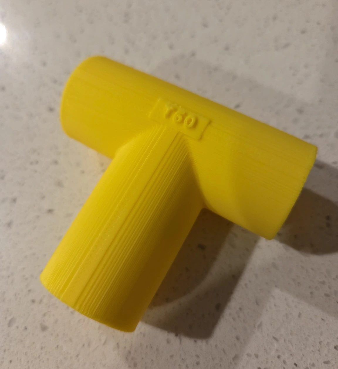
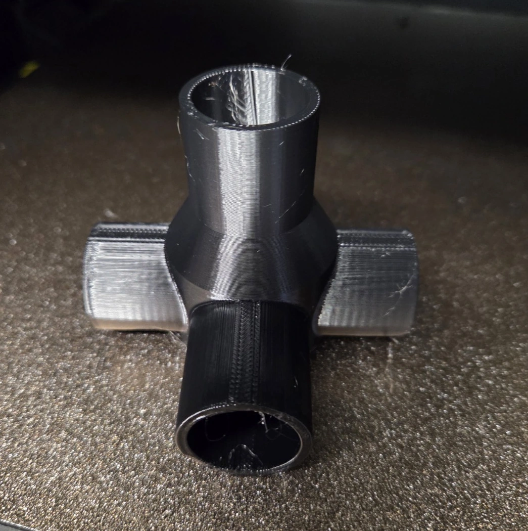
Original printed examples, not a guarantee of fit for another pole or filament. See the real build and its fit-test lessons →
This started with Dad's Aussie Gardener PestFree covers. He wanted to connect the separate rectangular garden frames into something bigger, so I made the missing T and then a four-way. These are independently made garden-frame joiners, not official Aussie Gardener fittings or water-carrying plumbing parts. Measure your own poles; compatibility isn't guaranteed.
How this works / What am I looking at?
Measure the pole first. The hole needs a little breathing room.
Lime: pole outside · Cyan: socket inside · Purple: optional stop
21.5 mm pole + 0.6 mm gap across the diameter = 22.1 mm hole. That is 0.3 mm on each side, not 0.6 mm on each side. The sketch is not to scale.
- Measure across the outside of your real pole with calipers, or a ruler if that is what you have. The receiving hole is the female socket; the pole going into it is the male part.
- Print the small test pieces (fit coupons) for each print orientation. Matching horizontal sockets share a set; the upright socket gets its own set, even when the numbers match.
- Try the real pole and write down the winning ID. The letters continue through the ZIP: for example H1-A to H1-E, then Z1-F to Z1-J.
- Apply that piece’s hole diameter to its listed connections. Generate another set and test the full-depth sample, supplied as STL and 3MF, before spending filament on the joint.
- Use the same filament, orientation and slicer settings for the final part. Check its slice and fit before putting it to work.
PLA taught me one fit. PETG had other ideas.
My PLA fit seemed good, then changing to PETG split a socket. I had to adjust the fit and add more material around it. The horizontal PETG sockets worked with a 22.1 mm receiving hole, 20.3 mm stop opening and 25 mm insertion depth. The fourth, upright socket’s 22.0 mm hole still needs its physical fit test. These are my results, not a universal recipe.
The same hole drawn in CAD can print differently lying sideways and standing upright. That is why the two sets stay separate. The short pieces find the fit; the full-depth pieces check the insertion depth and stop.
The optional internal stop is a smaller opening that catches the end of the pole. Turn it off for a passage without that shoulder. This is a garden-frame experiment, not a pressure-rated plumbing fitting.
1. Choose the junction and build volume
2. Start with matching sockets
These values reproduce our nominal garden PETG fit starting point. They are not universal filament settings. Enter measured pipe sizes and always validate with coupons.
Overrides include bore size, stopper, engagement and wall thickness. The upright port can use a different fit to the horizontal ports.
3. Extend the individual branches
Length is measured from the junction centre to each open end. This changes reach—not socket diameter or all-axis scale. Both X arms count towards the overall width. The complete solid, including its hub and the upright socket, must fit within all three build limits.