
THE GARDEN PROJECT // T + FOUR-WAY JUNCTIONS
Beyond the Rectangle
Garden T and four-way junctions
Dad’s garden netting kit was great at making little boxes. He wanted something bigger and more versatile, and I was tasked with making the T-junction to join it all together. A tiny T — and quite a lot of testing.
Where it's at
The PLA T60 worked. The grey PETG T60 cracked. Its pole fit was too tight, and the socket split when I pushed the pole in. T70 was the next idea, but it did not leave room for another 5 mm of pole capture in each socket as well as thicker walls. MakerMouse, my AI assistant, suggested T76 to fit both changes. The black T76 is the larger prototype shown with a real pole inserted. The browser generator now makes T and perpendicular four-way joints, but a completed file is not proof that a new size will fit. The four-way is now printed and physically fit-tested too. Its upright socket came out looser than the horizontal ones, so I kept separate fit-test pieces for the two orientations. The finished garden installation and outdoor use are still ahead.
Make your own T or four-way connector →
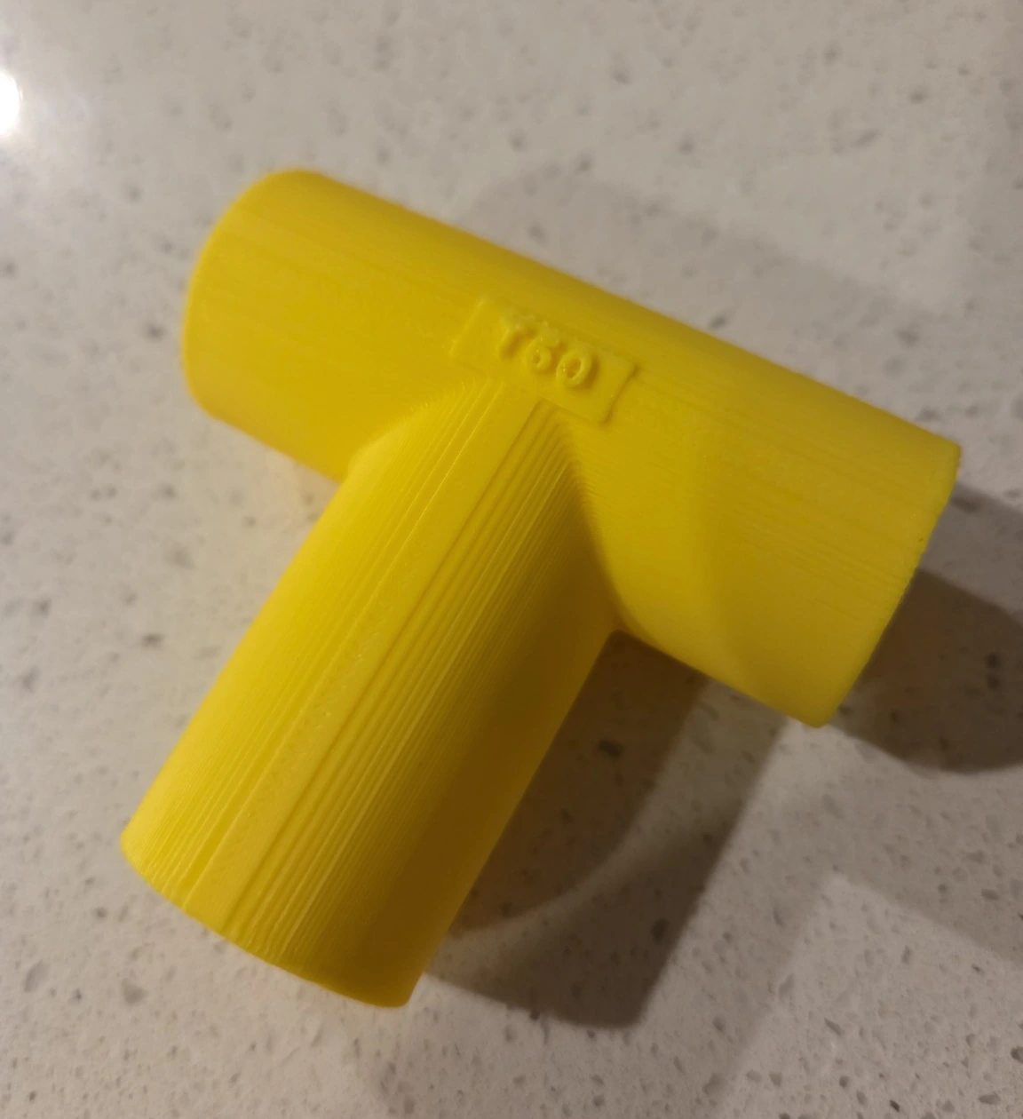
One garden bed was easy. Joining the next one was the problem.
Dad started with an Aussie Gardener PestFree garden cover. The poles, netting and corner fittings were doing a good job of protecting the fruit and veg, but the corners only made separate rectangular frames. Dad wanted a bigger, more flexible covered area, with longer runs and sections joined together. That meant making a different kind of connector.
The T and four-way are my own designs for that garden project, not official Aussie Gardener products. They started with his poles; other kits and sizes still need measuring and a test print. They are for garden-cover frames, not for carrying water under pressure.
A T-junction would let Dad connect two sections across the top and another from below. It's a small change, but it could turn several separate little boxes into a much more flexible protected area.
My ruler was not the precision instrument I wanted it to be.
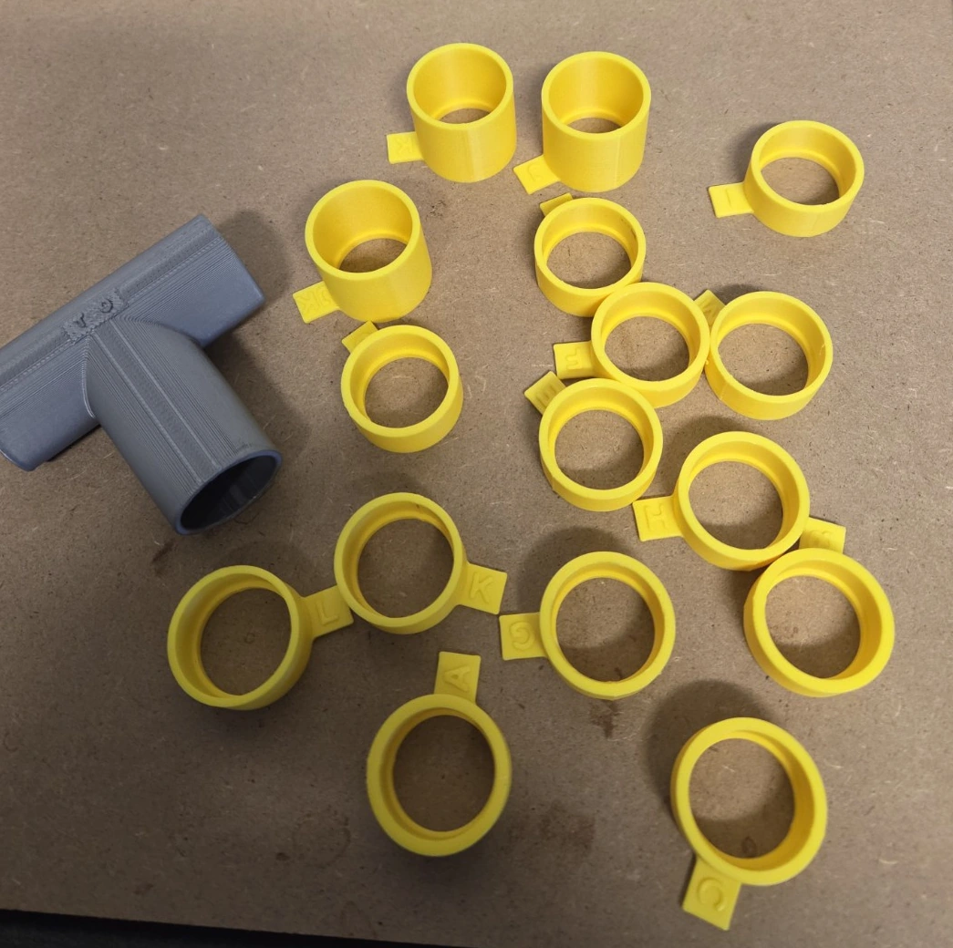
The existing plastic corners looked like they had roughly a 21 mm socket, with a smaller lip inside to stop the pole disappearing too far. We started there. The printer made some tidy little test rings.
Not one of the early ones would accept the pole.
That's the sort of failure I actually like finding on a ten-minute test piece instead of after printing a whole junction. We increased the opening in small steps, leaving each ring marked with a letter and a key recording what it measured.
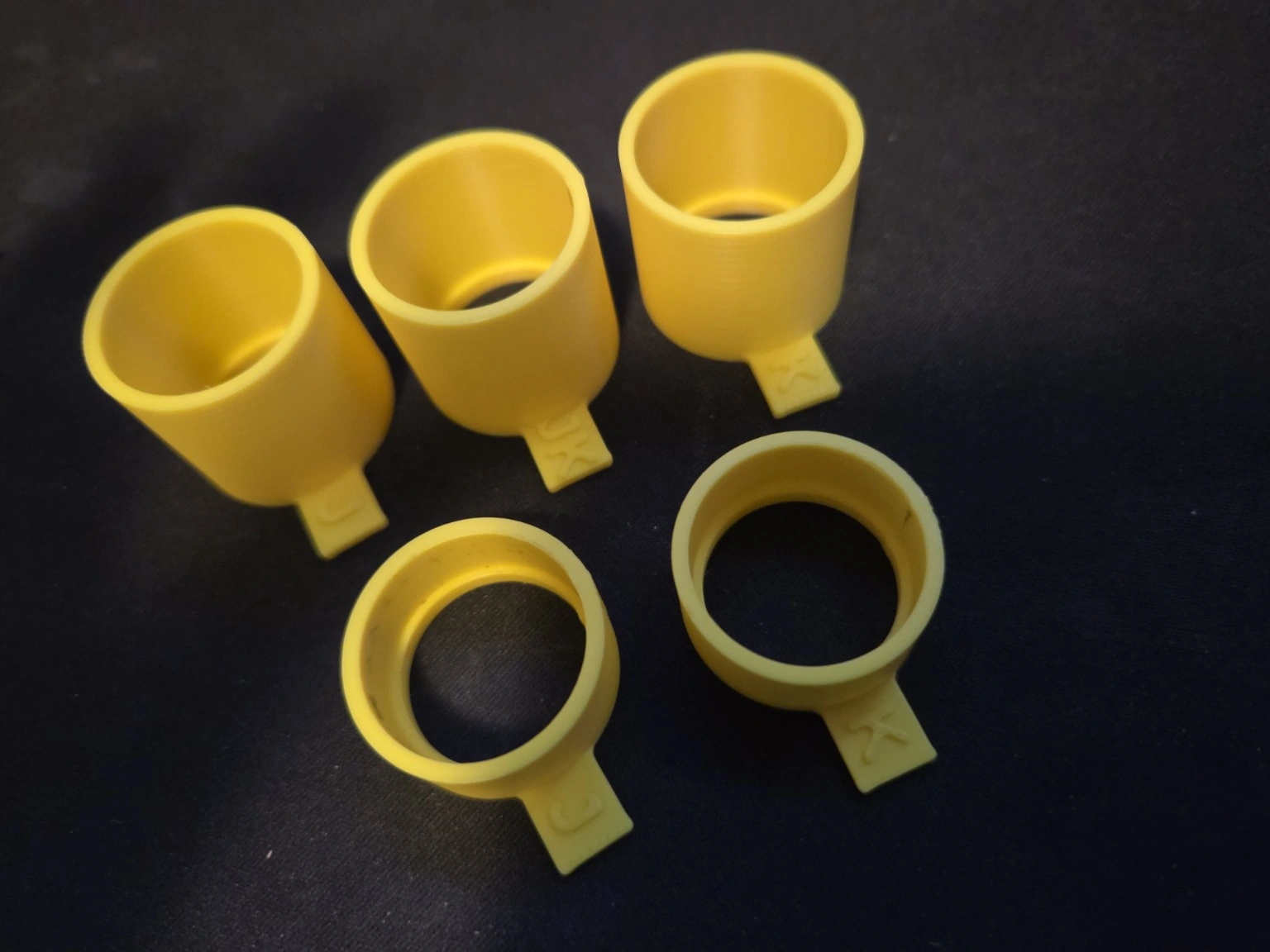
And yes, we briefly over-engineered the labels. I asked for more detailed markings, and MakerMouse, obligingly built bigger, fancier tabs. Printing took longer and used more plastic, for no useful improvement. The original A, B, C labels with a matching key were already enough. We went back to simple. Lesson learned.
Then we found Goldilocks.
J, at 21.6 mm, gripped too tightly. K, at 21.8 mm, was a little too loose. We split the difference and called it JK — 21.7 mm for the pole and a 19.9 mm opening through the stop lip. A full-depth, 20 mm test confirmed the PLA fit had the retention I wanted.
Flat printing: the slicer wasn't convinced.
We carried that proven JK socket into a single-piece T, with all three branches joined. I initially wanted a top bar around 50 mm wide, but the shoulders inside the sockets ran into the middle where the three tubes meet. The longer 60 mm version gave those stops more room, so that's the one I printed first.
Then Creality Print warned about unsupported areas inside the tubes. I tried an easy-to-remove support profile, changed the support options, and still got no supports generated. At that point I had a choice: redesign it before learning anything, or spend about 15 grams of PLA on a supervised test.
I pressed print and hoped for the best.
It worked. A few loose strands were left inside the openings where the printer bridged across thin air, and they made the fit slightly tighter until I cleaned them out. But the junction completed as one solid piece with no added supports.
PETG got its turn.
PLA had proved the basic shape, but I wanted PETG for a garden part. I printed the T60 again in silver-grey PETG. It finished without supports too, and the outside looked tidy. The little stringy bits and rough patches inside the socket were still visible, though. I'm not cropping away the interesting evidence to make it look more perfect.
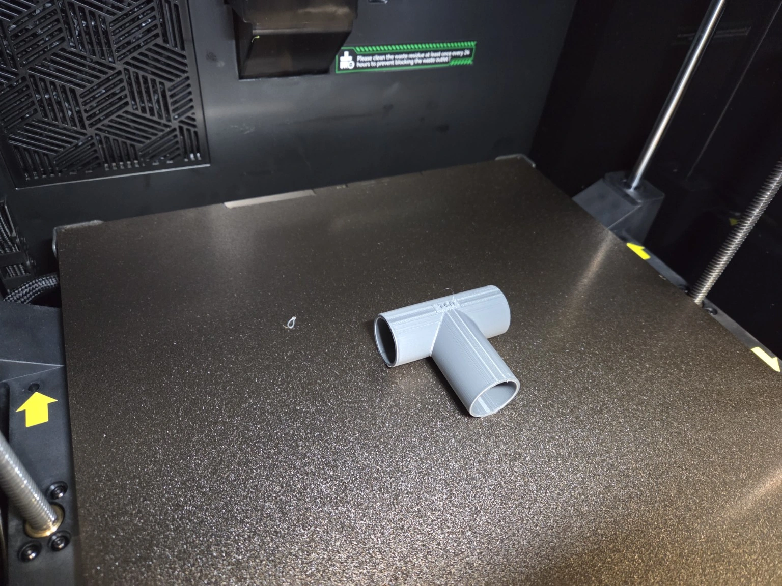
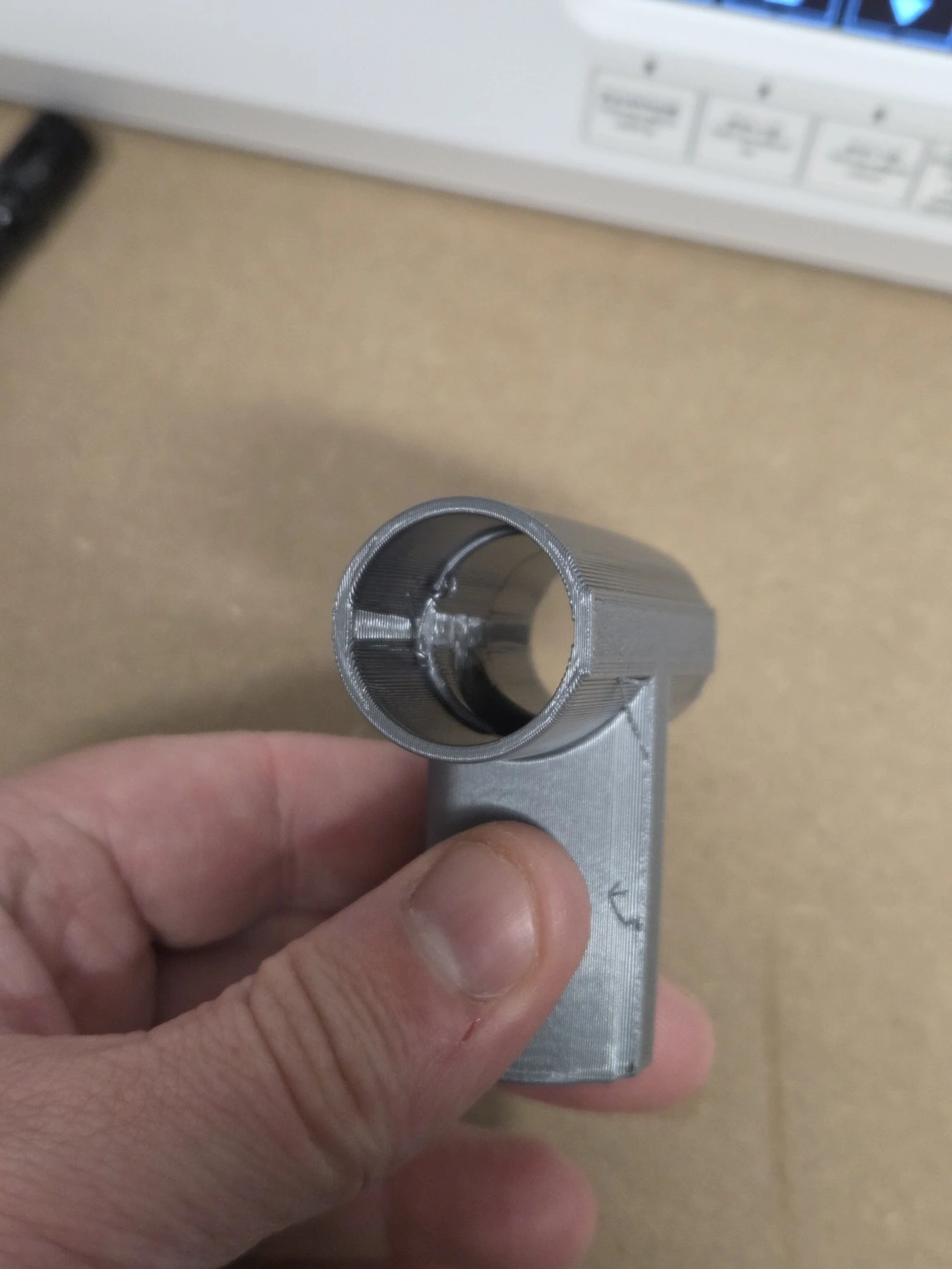
A tidy print. Then a very untidy fit test.
The silver-grey PETG T60 looked fine until I pushed in the real pole. The fit was too tight, and the socket split along its length. Same T60, different filament, very different result. The PLA test had shown the shape could work, but PETG still needed its own fit check.
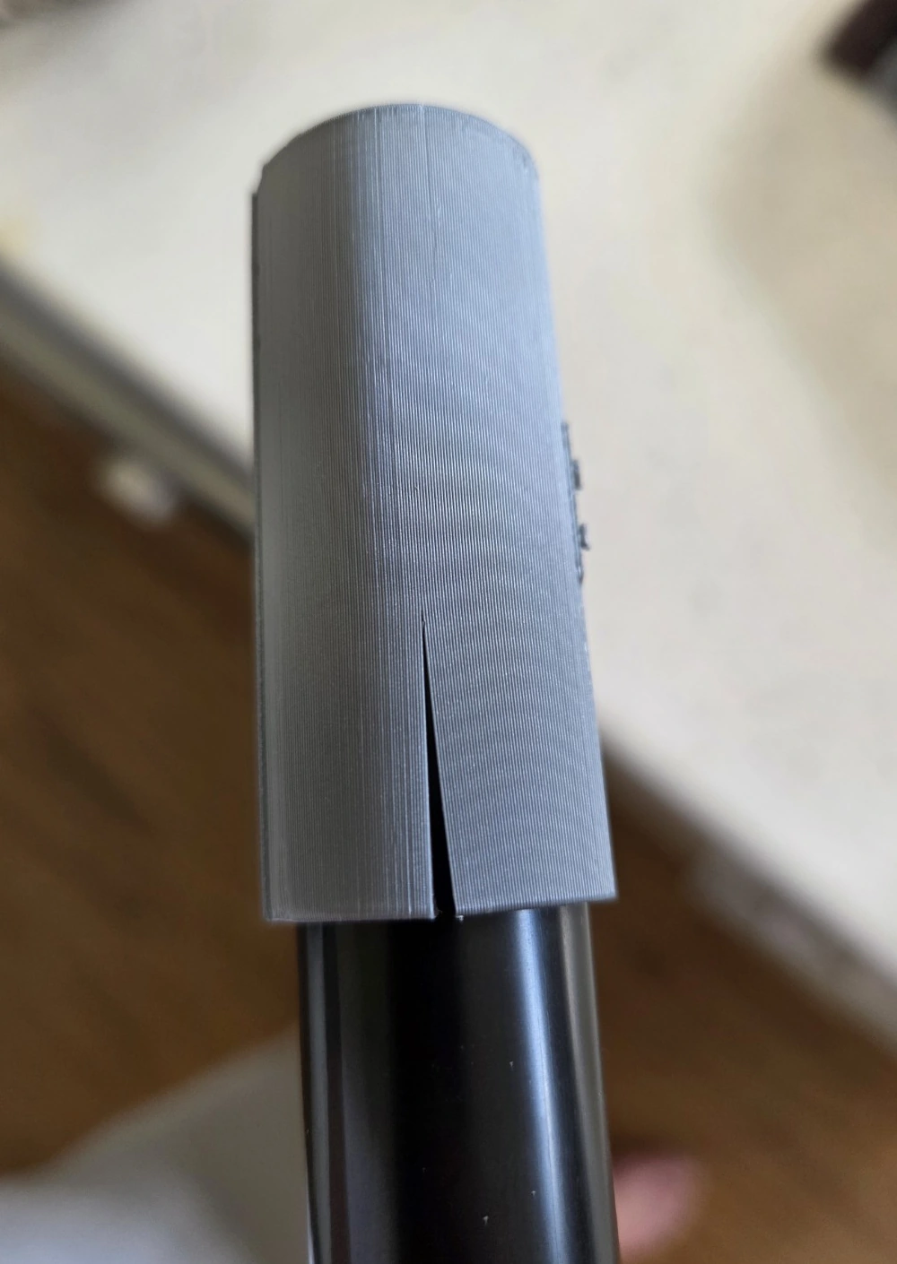
T70 looked good on paper. Then we counted the millimetres.
After the crack, I wanted two changes: thicker walls and another 5 mm of pole capture in each socket. T70 sounded like a reasonable next step, but there wasn't enough room for both changes once the sockets and their internal stops met in the middle. Rather than squeeze everything in and hope, MakerMouse suggested stretching the design to T76.
T76: more room where it mattered.
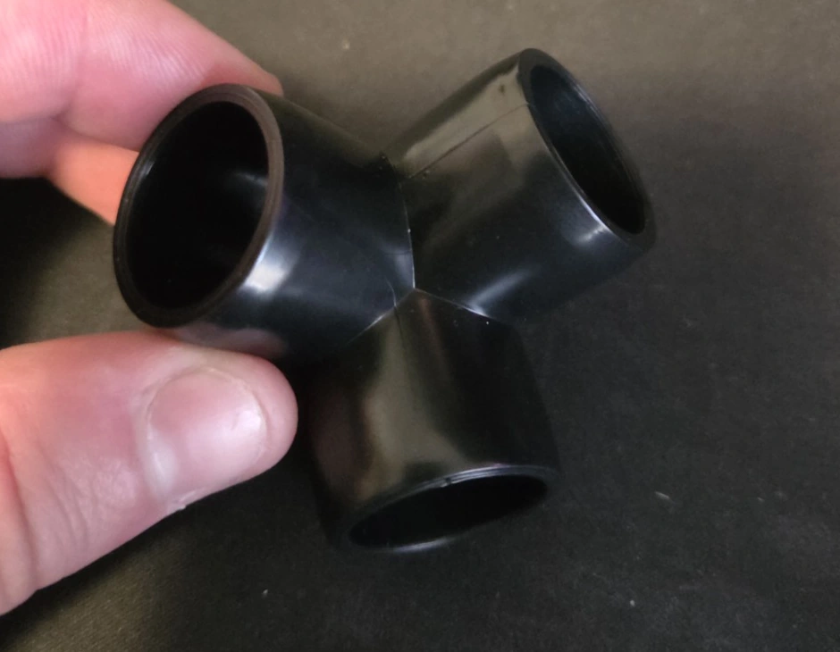
That gave us the space for the extra socket depth and thicker walls. I printed the larger T76 in black PETG and fitted a real pole for the photo below. It was a better starting point than the cracked T60, but the full garden setup still needs testing.
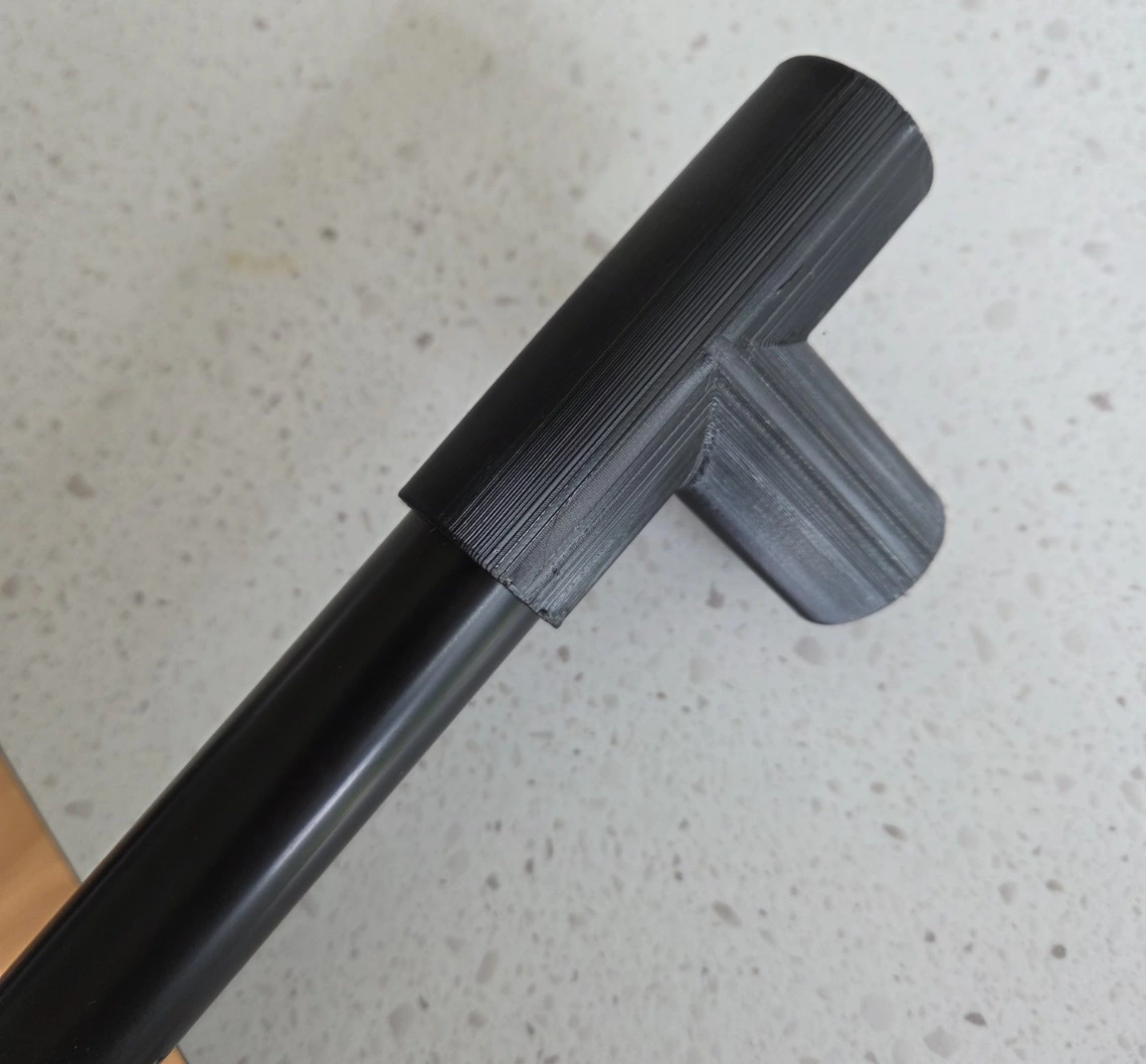
The later horizontal PETG fit work settled on a 22.1 mm receiving hole, a 20.3 mm opening through the internal stop, and 25 mm insertion depth. Those are the horizontal values I tested, not a universal PETG recipe or a measurement taken from this photograph.
T76 on the printer.
I also recorded a T76 print run. The clip shows the larger junction being printed. The real pole photo above is the fit evidence; the time-lapse is the print evidence.
One more direction: the four-way junction.
The T joins three branches in one plane. The perpendicular four-way adds another socket pointing up: that lets a longer frame run take an extra support pole back across the garden bed. That's what we designed it for; whether it holds up over a full garden season still needs testing. MakerMouse, helped turn all those measurement rounds into a browser tool that makes either shape.
I have now printed and physically fit-tested the black four-way. The horizontal sockets and the upright socket did not behave identically. The upright female socket, printed in a different orientation, came out wider-feeling and looser on the real pole. A completed print does not make every opening an equally good fit, even on the same part.
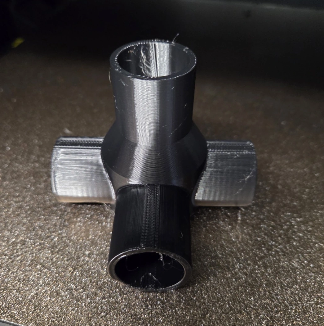
That's why the generator gives you separate horizontal and upright fit coupons — small labelled test prints for checking each direction with your own pole and filament. It also supplies full-depth samples, with STL and unsliced 3MF files. The originally trialled 22.0 mm upright setting is not a guaranteed recipe: the physical test showed why it needs its own calibration.
I also checked slicer previews of generated four-way and separate horizontal and upright test pieces. A slicer preview is useful for checking the files, but it cannot tell me whether a printed socket grips a real pole.
The generator starts with linked sizes, or you can tune each connection independently. A successful fit on this prototype does not guarantee a different generated size, filament or print orientation will fit; make the small test pieces first.
Try the fit before printing the whole junction
Measure the outside of your pole, choose the T or four-way shape, and start with the labelled samples. No CAD required. The generator’s help shows which edge to measure and why a little space around the pole matters.
Open the Garden & Tube Connector Generator →
STL and unsliced 3MF downloads need your own slicer settings. A generated four-way or a different size still needs its own print and fit check.
What still has to happen in the garden.
A larger netted area, normal handling and real outdoor use are the next tests. I do not yet know how the parts will hold up to weather and UV over time. These garden-frame experiments are not pressure-rated plumbing fittings.
The generator provides custom test files now. When a fixed model is ready for a public release, its listing will go to Creality Cloud, as usual.
The score so far
- Initial ruler-based sockets: failed fit.
- JK full-depth PLA coupon: good fit and retention.
- PLA T60: printed without supports; time-lapse recorded.
- Silver-grey PETG T60: printed, but the pole fit was too tight and cracked the socket.
- Proposed T70: not enough room for another 5 mm of capture per socket and thicker walls.
- Black PETG T76: thicker walls and deeper sockets; photographed with a real pole inserted.
- T76 time-lapse: a real print run of the larger design.
- Four-way: printed and physically fit-tested; upright socket looser than horizontal sockets.
- Separate horizontal and upright coupons: provided for orientation-specific fit testing.
- Garden assembly, outdoor handling and long-term use: still to test.
The split socket belongs in the story just as much as the better print. It is why the next version exists.